
Author: Mycond Technical Department
Effective microclimate control in spaces of various purposes is impossible without understanding the physical processes occurring in the air environment. One of the key issues that leads to improper operation of dehumidification systems is the uneven distribution of humidity within a space. Quite often, dehumidification systems operate inefficiently even with normal sensor readings due to local condensation in problem areas where humidity differs significantly from average values.
Physical mechanisms of water vapor mass transfer
The humidity distribution in a space is determined by two primary mass-transfer mechanisms: convective transport due to air movement and molecular diffusion driven by the gradient of water vapor concentration.
Convective transport occurs due to air movement and is the dominant mechanism in the presence of ventilation or natural circulation. The intensity of humidity equalization is directly proportional to air velocity and is determined by the volumetric airflow rate.
Molecular diffusion acts even in still air and is described by Fick's law: the mass flux of water vapor J = -D·(dC/dx), where D is the diffusion coefficient of water vapor in air (about 2.5·10^-5 m²/s under standard conditions), and dC/dx is the gradient of water vapor concentration.
The geometry of the space significantly affects the structure of airflows. In rooms with complex shapes featuring protrusions, columns, or partitions, stagnant air zones form where humidity equalization occurs mainly due to slow molecular diffusion.
Air stratification and vertical moisture content gradient
The vertical distribution of humidity in a space results from differences in the density of moist air at different heights. According to the ideal gas law, the density of moist air ρ = (Pdry·Mdry + Pvap·Mvap)/(R·T), where P is partial pressure, M is molar mass, R is the universal gas constant, and T is absolute temperature.
Since the molar mass of water vapor (18 g/mol) is lower than that of dry air (29 g/mol), warm humid air has a lower density and tends to rise. This creates natural stratification, with a layer of elevated humidity forming in the upper part of the space.
Stable stratification arises when there are sources of heat and moisture in the lower part of the space (people, technological processes) and there is no intensive mixing. The vertical humidity gradient can range from 2–3% relative humidity per meter of height in spaces with minimal air exchange to practically uniform distribution in rooms with intensive mixing.
Impact of the ventilation system and air distribution on parameter uniformity
The type of ventilation in a space determines how the humidity field forms. Consider three main schemes:
1. Mixing ventilation with supply to the upper zone — creates intensive mixing, ensuring relatively uniform parameters within the room volume. However, stagnant zones with elevated humidity may form near the floor and in corners.
2. Displacement ventilation with supply to the lower zone — forms an upward flow that removes moisture from sources of emission but creates a pronounced vertical humidity gradient.
3. Combined schemes — used for complex spaces and can provide the best uniformity through targeted organization of airflows.
The required volumetric airflow to ensure the specified uniformity is determined by the mass-transfer balance formula: L = G/(Cexh - Csupply), where L is the volumetric airflow rate, G is the moisture emission rate, and C is the water vapor concentration.

Local sources of moisture release and high-risk zones
Technological sources of moisture create zones of locally elevated humidity, whose radius of influence depends on evaporation intensity and ventilation effectiveness:
- Open water surfaces (pools, tanks) — continuous evaporation with an intensity up to 0.2 kg/(m²·h) at a water temperature of 20°C.
- Technological processes with evaporation — periodic or continuous sources with varying intensity.
- People — moisture release of 40–70 g/h per person at moderate activity.
Special attention should be paid to cold surfaces (enclosure structures, refrigeration equipment, pipelines), which are potential condensation zones. Condensation occurs when the surface temperature falls below the dew point of the surrounding air, even if the average indoor humidity is within normal limits.
Methodology for determining the number and placement of humidity sensors
Proper placement of humidity sensors is a key element of effective microclimate control. We propose a step-by-step methodology:
Step 1. Analyze the space layout and identify all sources of moisture release and cold surfaces.
Step 2. Determine the type of ventilation system and the directions of the main airflows.
Step 3. Identify characteristic zones: active ventilation, technological equipment, potential stagnation, near cold surfaces.
Step 4. Determine the need for a separate sensor for each zone using the criterion: if the zone has a local moisture source, a cold surface, or the distance from the active ventilation zone exceeds 5–7 meters, a separate sensor is required.
Step 5. Determine the sensor installation height depending on the type of ventilation and the purpose of the space.
Step 6. Placement check: no sensor should be located closer than 3 duct diameters to supply/exhaust.
Typical mistakes when designing humidity measurement systems
The most common mistakes when designing humidity measurement systems are:
1. One sensor for the entire room volume — it is impossible to ensure correct control of large or complex spaces with a single sensor due to spatial non-uniformity of parameters.
2. Placing the sensor in the supply/exhaust airstream — such a sensor will measure supply/exhaust parameters rather than actual parameters in the working zone.
3. Ignoring temperature stratification — placing the sensor at a height that does not correspond to the critical control zone.
4. Lack of monitoring near cold surfaces — this is exactly where the highest risk of condensation occurs, even at normal average humidity.
Operational consequences of incorrect sensor placement
Incorrect placement of sensors leads to serious operational problems:
1. Sensor in the active air-exchange zone: shows normal humidity (40–60%), but in stagnant zones humidity is elevated (70–90%) and condensation occurs. Consequences: product damage, corrosion, growth of microorganisms.
2. Sensor near a local moisture source: constantly shows elevated values (60–80%), the dehumidification system runs at maximum. Consequences: 30–50% excess energy consumption, overdrying other zones down to 20–30% relative humidity.
3. Sensor at the wrong height: for example, under the ceiling it shows elevated humidity (60–70%), although in the working zone it is normal (40–50%). Consequence: wasteful operation of the dehumidifier.
Limitations and conditions for adjusting the above approaches
The proposed methodology has certain limitations:
1. In spaces with a volume over 10,000 m³, even correctly placed point sensors may not provide complete control — a distributed monitoring system is required.
2. At temperatures below -20°C, the accuracy of standard capacitive humidity sensors decreases — special sensors are needed.
3. In environments with elevated dust content or aggressive substances, standard sensors quickly lose calibration — protective housings or special sensors are required.
4. With seasonal changes in operating mode, recalibration of sensors or even changes in their placement may be necessary.
FAQ: questions and answers about humidity control
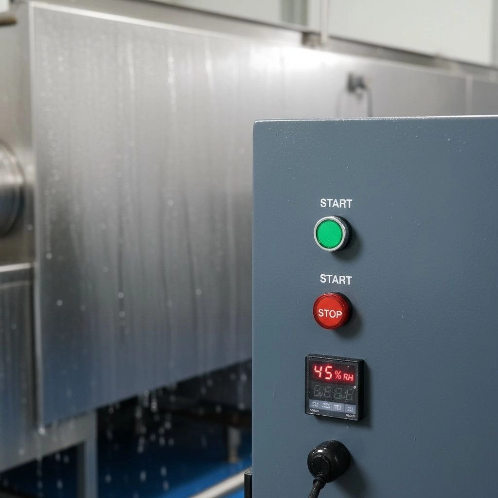
1. Why does condensation form on walls when sensor readings are normal?
This is a typical example of local humidity non-uniformity. If the surface temperature of the wall is below the dew point of the surrounding air, condensation will occur even at overall normal humidity. The difference between a sensor reading at the center of the room and near a cold wall can reach 15–20% relative humidity.
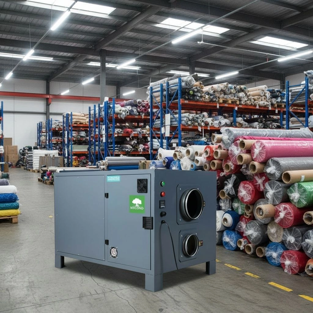
2. How many sensors are needed in a 1000 m² warehouse?
For a warehouse with an area of 1000 m², the minimum number of sensors is determined by the formula: N = 1 + (S/300) + Nsources + Ncold, where S is the area of the space, Nsources is the number of powerful moisture sources, and Ncold is the number of zones with cold surfaces. For a standard warehouse without special moisture sources, this is usually 4–5 sensors.
3. At what height should a humidity sensor be installed?
The installation height depends on the type of ventilation: for mixing ventilation — at working-zone height (1.5–1.8 m); for displacement ventilation — at the level of the technological process or the zone of maximum condensation risk; for multi-tier spaces — separately on each tier.
Conclusions
Proper placement of humidity sensors is not a formal requirement but an engineering necessity that follows from the physics of water vapor mass transfer in air. Practical recommendations for designers:
1. Always analyze the structure of airflows before determining control points.
2. Consider local sources of moisture and cold surfaces as key factors of non-uniformity.
3. Do not skimp on the number of sensors if justified by the size and complexity of the site.
4. Periodically check the correlation between readings of different sensors to detect anomalies.
5. Remember that a single sensor is almost never able to provide reliable control in large industrial spaces.